
HDMI TYPE A · 19 CONTACTS
HDMI port pinout
One connector. Nineteen pins. Explore the signals behind your picture, sound, and device connection.
This HDMI Type A pinout explains each contact on the standard full-size connector used by many consoles, TVs, monitors, and laptops. Trace the signal groups in the interactive explorer or jump to the complete pin table.
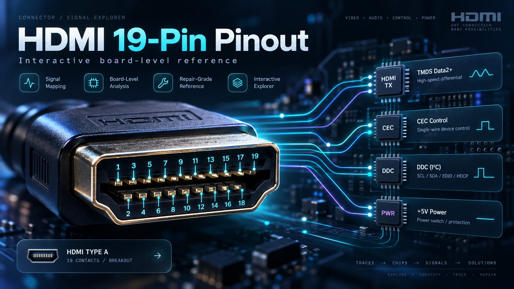
Before you trace a pin: check the viewing direction
The explorer shows functional signal paths, not physical pin positions. A plug mating face, socket mating face, and rear solder-pad view can appear mirrored. Identify pin 1 using the exact connector manufacturer's drawing before tracing a board. Do not use the artwork above as an orientation guide. Mini HDMI (Type C) and Micro HDMI (Type D) also have 19 contacts, but their pin assignments differ.
Interactive HDMI 19-pin signal explorer
Select a pin to highlight its typical circuit path. Search by pin number or signal, filter by group, or expand the diagram. On smaller screens, swipe the diagram horizontally.

Open the explorer in its own tab ↗ · The full reference below works without JavaScript.
HDMI Type A pinout table: all 19 pins
These are connector contact numbers, not IC package pin numbers. The names below describe the conventional TMDS signal assignment; supported FRL modes reuse the high-speed pairs.
| Pin | Signal | Function |
|---|---|---|
| 1 | TMDS Data2+ | Positive conductor of the Data2 differential pair in the high-speed HDMI path. |
| 2 | TMDS Data2 Shield | Shield / ground return for the Data2 pair. This is not a data input on the HDMI IC. |
| 3 | TMDS Data2− | Negative conductor of the Data2 differential pair in the high-speed HDMI path. |
| 4 | TMDS Data1+ | Positive conductor of the Data1 differential pair in the high-speed HDMI path. |
| 5 | TMDS Data1 Shield | Shield / ground return for the Data1 pair. Actual shield bonding follows the board design. |
| 6 | TMDS Data1− | Negative conductor of the Data1 differential pair in the high-speed HDMI path. |
| 7 | TMDS Data0+ | Positive conductor of the Data0 differential pair in the high-speed HDMI path. |
| 8 | TMDS Data0 Shield | Shield / ground return for the Data0 pair. This path belongs to the ground / shield network. |
| 9 | TMDS Data0− | Negative conductor of the Data0 differential pair in the high-speed HDMI path. |
| 10 | TMDS Clock+ | Positive TMDS clock conductor. In four-lane FRL operation, the clock pair is reused as a data lane. |
| 11 | TMDS Clock Shield | Shield / ground return associated with the TMDS clock differential pair. |
| 12 | TMDS Clock− | Negative TMDS clock conductor. In four-lane FRL operation, the clock pair is reused as a data lane. |
| 13 | CEC | Single-wire Consumer Electronics Control bus for device-control communication. |
| 14 | Utility / HEAC+ | Optional auxiliary / HEAC path. Implementation varies; do not assume this pin is populated on every board. |
| 15 | DDC SCL | DDC I²C clock used for display information (EDID) and HDCP communication. |
| 16 | DDC SDA | DDC I²C data used for display information (EDID) and HDCP communication. |
| 17 | DDC/CEC Ground | Ground reference for the DDC and CEC control signals. Not a separate signal-processing IC. |
| 18 | +5V Power | HDMI source power path, typically through a supply / protection circuit rather than a high-speed IC output. |
| 19 | HPD / HEAC− | Hot Plug Detect from the display toward the source. HEAC− shares this pin in supported implementations. |
What do the HDMI signal groups do?
High-speed pairs: pins 1–12
TMDS carries video, audio, and related packets across three differential data pairs plus a clock pair. In supported four-lane FRL modes, the clock pair becomes another data lane. Each pair has an associated shield contact.
CEC: pin 13
Consumer Electronics Control is a shared, single-wire control bus. It enables compatible devices to exchange commands such as power and input selection; it is not a video signal.
DDC: pins 15–17
SCL and SDA form the Display Data Channel, with pin 17 providing the control-signal ground reference. The source uses DDC to read the display's EDID capabilities and exchange HDCP information.
Power and detection: pins 18–19
Pin 18 supplies +5 V from the source. Pin 19 carries Hot Plug Detect from the display to the source. Detection and display-information exchange help establish a connection before normal video transmission.
Utility / HEAC: pins 14 and 19
Pin 14 is the utility / HEAC+ contact; pin 19 shares HPD with HEAC− in supported designs. Auxiliary functionality depends on the implementation, so a generic diagram does not establish whether a board supports it.
Ground and shielding
Pins 2, 5, 8, and 11 are pair shields; pin 17 is the DDC/CEC ground reference. The connector's metal shell is separate from the 19 signal contacts. Exact bonding and protection follow the board design.
Using the pinout to understand HDMI faults
A bent contact, cracked solder joint, damaged pad, or failed protection component can interrupt a connection. But a “no signal” message alone cannot identify the failed pin or prove the port needs replacing.
First try a known-good HDMI cable and a different display input. Inspect an unpowered connector for visible damage. Board-level measurements require the correct connector drawing and board documentation; never bridge adjacent contacts or assume a resistance value from this generic guide.
HDMI pinout questions
How many pins does a standard HDMI port have?
The full-size HDMI Type A connector has 19 signal contacts. The metal shell is not counted as a twentieth signal pin.
Which HDMI pin supplies power?
On Type A, pin 18 is the +5 V source supply. Pin 19 is Hot Plug Detect, not a second power-supply pin.
Do HDMI 2.0 and HDMI 2.1 use different Type A pinouts?
The Type A connector retains its 19 contacts. The high-speed signaling mode can change: TMDS uses three data pairs and a clock pair, while four-lane FRL reuses the clock pair as data. Connector appearance alone does not establish bandwidth support.
Can I use this diagram for PS5 or Xbox solder pads?
It explains Type A contact functions, not a console motherboard layout. Identify the exact replacement connector and board revision, then use their documentation to establish pad orientation and routing.
Technical references
Signal assignments: Wilder Technologies Type A HEAC test-adapter manual. TMDS/FRL channel use: AMD HDMI PHY Controller documentation. Protection and control circuits: Texas Instruments TPD12S016 datasheet.
Generic educational reference. Exact ICs, protection components, and routing depend on the board. HDMI is a trademark of HDMI Licensing Administrator, Inc.; this guide is not an official HDMI specification.